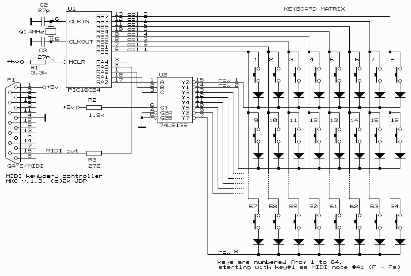
A minimum number of parts are used to achieve minimal cost and easy construction. The parts are:
U1: A PIC16C84, the famous single-chip controller by Microchip, which is the core of this device;
U2: A 74LS138, which is a 3-to-8 decoder, used to scan the keyboard dynamically;
Q1, C2, C3: A 4 MHz quartz resonator, and 2 capacitors needed for the PIC's internal clock generator;
R1, R2: 2 resistors to pull up specific IC pins (on U1 and U2) to Vcc (which is +5v supplied from pin 1 of the soundcard's DB-15 gameport);
R3: A protective resistor;
D1...: Generic Si diodes to prevent short-circuiting of 74LS138 outputs, and false keycrossing events, by simultaneously pressing a group of keys upon the piano keyboard;
4 octave keyboard matrix: A total of 48, 7*8 keyboard switches. One switch is placed under each key of the keyboard;
DB-15 (male) connector: to connect to the soundcard's MIDI/Game (joystick) port.
There is no need for a power supply unit built into the keyboard. The keyboard obtains its power from one of the pins upon the soundcard's DB-15 connector. This means that a high voltage is not required, and also the cost is significantly reduced. The only potential hazard is that you could damage your soundcard by improperly wiring the keyboard's DB-15 connector. Be very careful to double-check the wiring before testing.
This MIDI keyboard is therefore intended to work in conjunction with a PC soundcard. If you wish to use it directly (ie, without the soundcard) with other MIDI devices, you should consider making it self-contained by building a power supply, and also buffering MIDI signals in a standard way as described in many articles found on the Internet.

To mount the ICs, resisters, diodes, and other parts, a universal PCB is used with a size of approx. 5x5 cm. As you can see in the picture below, there are four connectors: the first is for MIDI cable, the second is for keyboard matrix column cable, the third is for keyboard matrix row cable, and the fourth is for PIC onboard programmer.

For the piano keyboard itself, I used an old keyboard from a simple 4-octave analog synthesizer, adding switches (buttons) to it beneath every key. As you can see in the below photos, it is not very pretty, but it works fine.


You can successfully adapt almost any kind of keyboard. There are a lot of inexpensive keyboards (often called "sound banks" or something similiar) in toy-shops, which can be easily adapted for this purpose. Alternately, you could even create a set of some sort of drum triggers rather than using a piano keyboard.
I have supplied a file containing the assembled hex code of some microcode I wrote for the PIC16C84. This hex file was generated (from my microcode) by the Microchips MPASM utility. At this time, I do not intend to publish my microcode in source form. The hex code is all you need (and a PIC programmer of course) in order to put my microcode on the PIC chip. This microcode of course allows the PIC to perform its scan of the piano keyboard, and turn key presses into MIDI data transmitted to the soundcard's DB-15 MIDI In pin.
This version of microcode doesn't support additional buttons for mode switching. I'm currently working upon adding this support. When an update is ready, I will publish it.
Download the PIC16C84 microcode.
Also available for download is a version of Microsoft's MIDIMON program to run upon your computer. Using this software, you can play the built-in sound module of your soundcard using the MIDI keyboard. Simply select the MIDI In of your soundcard as the software's input, and select MIDI Mapper as the software's output. (You can additionally control other external sound module's attached to your soundcard's MIDI Out). Of course, most sequencer programs already have this functionality built into them, but this software is freely provided for those who do not have any such sequencer software.
I've also tested the MIDI keyboard with CAKEWALK and it works fine. The keyboard should work with any MIDI software that can utilize your soundcard.